Criteria for Choosing Microcontroller
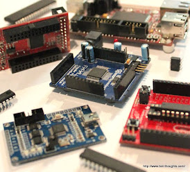
Criteria for Choosing Microcontroller


Choose Microcontroller


Hi, Selecting an microcontroller is one of the daunting task even for an experienced developer.
The one of the critical decision of your embedded application is to select the right microcontroller which control the failure and success of your project. 

There are thousands of type of microcontroller each of them has unique feature or advantage from form factor or package size ,capacity of random access memory & read only memory that made them fit for certain application and unfit for  certain application.

Microchips portfolio for microcontroller is broadest in industry.it includes ARM,PIC & AVR microcontrollers. Primarily experience with one these architecture is valuable and staying with that architecture reduced the development time. They also offer easy to use development environment and development board which reduced research time and cost.

Consideration are important to pick the right part. The common profile of the principal benchmark in selecting a microcontroller is listed here in the order of importance.

1-Does it have a the required number of I/O pins ? like too few pins can not meet the application requirement and too many increases the size of printed circuit board in result excessive development cost.

2-Does it have all the other required peripherals? like enough memory to run the required code ,resolution of analog to digital converter, number of timers and pulse width modules.

3-Does it comes in a 40pin DIP(dual inline package)or a QFP(quad flat package) or some other packaging format? This is critical for development and assembling point of view for the final product.

4-Does it have necessary communication interface? These are peripherals such as USB,I2C,SPI,UART and CAN(control area network).

5-Does the CPU core have the correct throughput? For example, computational power to handle the system requirements over the life of the system for the chosen implementation language? if controller has ability to perform 32 bit operations, it can transfer more data than 8 bit microcontrollers. it based on application requirement, for an 8 bit based embedded application 32 bit microcontroller considered to be excessive resource.

6- Is development support available? like Assemblers, compliers, Evaluation module, In-circuit emulators, debug monitors, online bulletin board service, bug reports Utility software and sample source code.   

Friends if you have any other point related to criteria for choosing microcontrollers please comment and for further reading about how to find relevant microcontroller checkout
 

Comments

Popular posts from this blog

How to use SPI Debugger

  SPI Debugger Hi Friends, in this post, we will discuss how to use SPI Debugger available in proteus for serial peripheral interface (SPI) which is a built-in feature of PIC microcontroller to communicate and data exchange between PIC and other devices. SPI Debugger Introduction to SPI Guys, SPI can be considered as a programmable shift  register, The SPI module is a synchronous serial I/O port that shifts a serial bit stream of variable length and data rate between the PIC and other peripheral devices. Here “synchronous” means that the data transmission is synchronized to a clock signal. To avoid further delay, let's see some important connections and different configurations to effectively use SPI Debugger. How to use SPI Debugger in MASTER & SLAVE configuration Select the virtual instrument and from the instrument, list selects "SPI Debugger". SPI Debugger Insert two SPI Debugger on the working area, select any one of them,

PIC18f4580 Timer0 calculation using miKroC , CSS and proteus

PIC18f4580 TIMER PROGRAMMING The PIC18f4580 has four timers. they're named as Timers zero, one, two, and three. they will be used either as timers to come up with a time delay or as counters to count events happening outside the microcontroller. First, we see however Timers zero is employed to come up with time delays. Every timer wants a clock pulse to tick. The clock supply will be internal or external. If we have a tendency to use the inner clock supply, then 1/ fourth of the frequency of the crystal oscillator on the OSC1 and OSC2 pins (Fosc/4) is fed into the timer. Therefore, it's used for time delay generation and for that reason is termed a timer. By selecting the external clock choice, we have a tendency to feed pulses through one among the PIC18's pins: this is often known as a counter. GIF  taken from  https://exploreembedded.com Basic registers of the timer Majority of t timers in 18F are 16 bits wide. Because the PIC 18 has an 8- bit ar

Frequency Counter using Interrupts PIC18f4580 Project

Frequency Counter  using PIC18f458 0 Proje ct This POST describes the construction of small frequency counter with a cheap PIC18f4580 microcontroller with 16 x 2 LCD.   Prerequisites: PIC18F4580 TIMER Programming. PIC18F4580 COUNTER Programming. PIC18F4580 Interfacing with 16x2 LCD. PIC18F4580 Interrupts Programming  ( we will cover in this POST) Concept: Frequency  is the number of occurrences of a repeating event per unit time. in our case we will measure a number of clocks generated by clock source per unit time. In this project, LCD is used to display the frequency and PIC timer 1 to measure the input signal and Timer0 to generate an indication that one second has gone. System software utilizes Timer-1 in the 16-bit counter mode to count the input signal and overflows of the counter are added to provide the aggregate count in multiples of 65536. Totaling the existing value of the counter at the conclusion provides the full count.